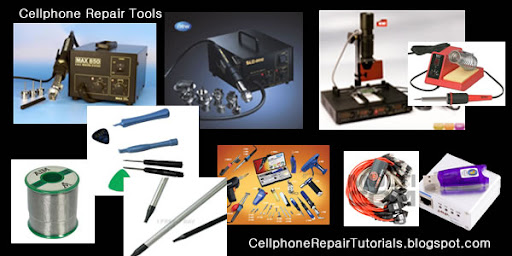
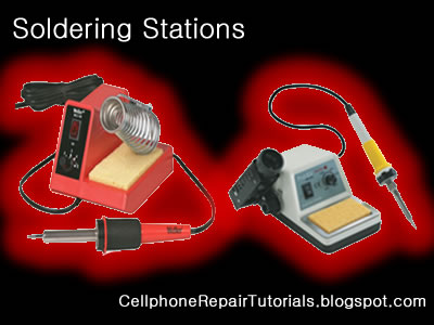
04/06/14 ~ Rayerbazar Mobile
Rayerbazar Mobile Apps For Android Phone
Rayerbazar Mobile Any Password Protected File Post... Go This Link For Password and Search Dont Mind Friend
.::Shohag Mobile Technology::. Rayerbazar, Dhaka-1209. All Kinds OF Mobile Solution HERE....... iPhone, Samsung, Nokia, Blackberry, LG Flash & Unlock Email-shohag.proyes@yahoo.com Mobile No.+8801618405155
Attention Please:


"
All My Sweet Friends When any File download Please Read Full Information then Download File ( All Flash File Full Free No Need Cost "Thanks" )

06 April 2014

Soldering Tools

Soldering Iron
A soldering iron is a tool normally used for applying heat to two or more adjoining metal parts such that solder may melt and flow between those parts, binding them securely, conductively and hermetically.

A soldering iron is composed of a heated metal tip and an insulated handle. Heating is often achieved electrically, by passing an electrical current (supplied through an electrical cord or battery cables) through the resistive material of a heating element. Another heating method includes combustion of a suitable gas, which can either be delivered through a tank mounted on the iron (flameless), or through an external flame.

Some soldering irons heat up and cool down in a few seconds, while others may take several minutes.
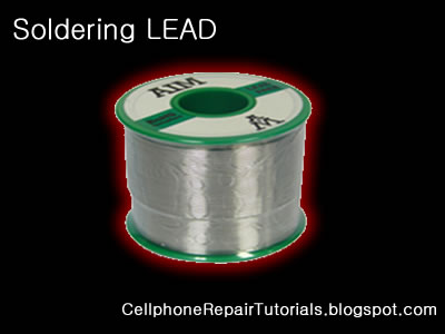

Soldering LEAD
 Soldering lead is used to bond or connect electronic components.
Solder is a fusible metal alloy with a melting point or melting range of 90 to 450 degree Celsius (190 to 840 °F), used in a process called soldering where it is melted to join metallic surfaces. It is especially useful in electronics . Alloys that melt between 180 and 190 °C (360 and 370 °F) are the most commonly used. By definition, using alloys with melting point above 450 °C (840 °F) is called brazing. Solder can contain lead and/or flux but in many applications solder is now lead free.

While it is possible to do some wiring without soldering connections, soldering is the preferred approach. Proper soldering is easy with the right tools and techniques. One item that is critical is the right solder. DO NOT use the environmentally friendly lead free solders, they don't work worth a damn. Even in carefully controlled industrial conditions, lead free solders produce inferior connections. As much as the politicians backed by environmentalists would like to, they can't legislate metallurgy.
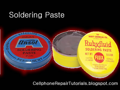
Soldering Paste
Solder paste (or solder cream) is used for connecting the terminations of integrated chip packages with land patterns on the printed circuit board. The paste is applied to the lands by printing the solder using a stencil, while other methods like screening and dispensing are also used. A majority of defects in mount assemblies are caused due to the issues in printing process or due to defects in the solder paste. An electronics manufacturer needs to have a good idea about the printing process, specifically the paste characteristics, to avoid reworking costs on the assemblies.

Characteristics of the paste, like viscosity and flux levels, need to be monitored periodically by performing in-house tests.

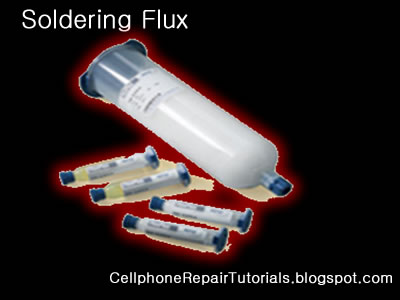
Soldering flux Soldering flux is just a safe, convenient acid for dissolving the oxide skin off the metal
you want your solder to wet well. Also dissolves oxide off the liquid solder, making it
less crusty and therefore more shiny.

"Acid" flux is the stronger class of flux; it has something like hydrochloric acid in
it. (The paste form has zinc chloride.)
This is good for making difficult oxides dissolve so difficult metals like stainless
steel can be solder-wetted.
But the acid can hang around later trying to corrode the metal it just cleaned for you.
So for electronic stuff we mostly do not use it.
If we do, we scrub it off with things like toothbrush, water, soap, alcohol, baking soda,
to minimize acid residues.

The flux built into most solder wire is called rosin flux.
I think it is an organic acid (so is vinegar, and tart-tasting "citric acid"),
stuck onto larger molecules that melt only at soldering temperatures.
That is the clear yellow-brownish plaque that sits on the solder's surface when you are
done.
It does the same stuff as acid flux, but it is milder two ways.
It is only strong enough to reduce weakly oxidizable metals like copper, tin, lead,
silver.
So it is just strong enough for electronics use, but not for soldering to stainless
steel or iron or anything with chrome or aluminum.
And rosin-flux goes back to its plastic-like solid form after use, so it does not act
very corrosive to the metals later on.
So we do not need to clean it away carefully.
It can be cleaned away if you want to work at it, with brush-scrubbing and the right
"polar solvents".
"Flux remover" is sold in spray-cans for this. Rubbing alcohol with a dash of dish-soap
sort of works for me.
Try it and see what it looks like.
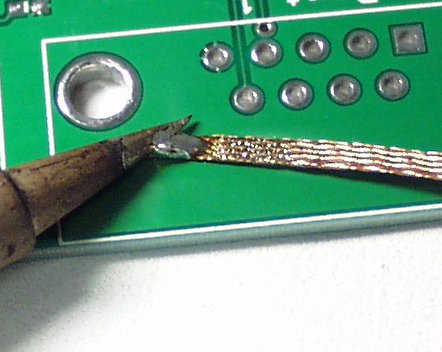
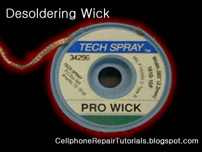

  Soldering Wick
A solder wick (also desoldering wick or desoldering braid) is a tool for removing solder from any solder joint. Usually, it is a roll of fine, braided 18 to 42 AWG wire, typically oxygen free copper, which has been treated with a rosin solder flux.


Close up to a piece of solder wick


Close up to the netting of a solder wick


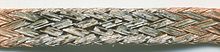
To remove solder with it, one presses the wick onto the solder joint to be removed and then heats the wick portion that is on the connection with the tip of a soldering iron. As the rosin melts onto the wick and the connection and the solder reaches its melting point the solder rushes via capillary action onto the clean copper braid. Once everything has melted and the solder fuses with the braided copper, the wick is lifted along with the solder and is then cut off and disposed of.

Mobile Dissemble tools


Opening Tools

Proper opening tools is used to avoid damaged and insure safety in handling mobile phones, which prior to avoid risk of scratches and breakage.

Free-Cellphone-Repair-Tutorials

Tweezers
Tweezers are tools used for picking up small objects that are not easily handled with the human hands and very useful in surface mounted electronics components.
Free-Cellphone-Repair-Tutorials

Torx and Precision Screwdrivers
Various Mobile phone uses variety of screws mounted to every products.
Free-Cellphone-Repair-Tutorials
Do not try to attempt opening any screws that did not match with the screwdriver you have or you might end up a loosen tread screw, and find it hard enough to open it up...
Selecting and collecting of Torx and precision screwdrivers is highly recommended.
Torx and Precision comes with different code and number..
T6 is the most commonly used in mobile phones.

Mobile Phone Repairing Tools

Preparing the Proper Tools For Repairing..


There are many different variety and Cellphone Repair Tools. A lot companies offers online purchasing for such certain tools for beginning into business... You can choose which is which for such certain product.
In my opinion, when you are into a planning to purchased any tools, Ask some experts first for that certain products you are going to buy...


Free-Cellphone-Repair-Tutorials
Basically these are the primary tools when you are going to repair cellphones.

1. Multi-Tester ( Analog/Digital)- Used to measure Voltages, Currents and Resistance in electronic components.

2. Screwdrivers - Used to loosen the phones screws.

3. Tweezers - used to hold and pick small cellphone component parts.

4. Soldering iron - used to solder / resolder  electronic parts.

5. Soldering lead - used to bonds Electronic components.

6. Soldering Flux and Paste - Used to tightened soldering quality.

7. BGA Rework station - Applied Heat  to  remove and replaced parts and  IC chips.

8. Re balling Kits - Tools for re balling IC bumps, this composed of Stencil plates, Ball Leads and Spatula

9. DC Regulated Power Supply- Used to substitute battery voltage when working on hardaware troubleshooting.

10. Flashing and Unlocking Device- it is Software Tools that used to unlock and flash mobile phones
                                                         programmable circuits.

11. Cables and Wires - Used as an Interface from PC to cellphones when working on like flashing, unlocking
                                      and jailbreaking.


Test Equipment

Electronic test equipment  is specialized equipment which is used in the testing of electronics. It can be utilized in the construction of prototypes and new products, and in maintenance and troubleshooting. A huge family of components are included under the umbrella of electronic test equipment, ranging from simple equipment which is used for routine home repair to sophisticated systems which are used exclusively by engineers. Many companies sell used electronic test equipment, which is often far less costly than brand new products and just as useful.
All of the devices in the family of electronic test equipment are capable of providing some sort of information about an electronic device or circuit. This information can vary from something simple, like whether or not current is flowing through a circuit, to something complex, like whether or not the components of a motherboard  are working properly. Electronic test equipment may be passive, or it may emit an active signal and register a response, and it can provide specific measurements, or more generic data.

Typically, electronic test equipment includes a way to interface with an item being tested, such as a probe or clip, and a readout which provides information, ranging from a light which becomes illuminated when something is working properly to a readout with measurements. Sophisticated equipment may hook up to a computer for the purpose of performing diagnostics, with the equipment running several different tests at once and compiling the information in a computer program. This type of electronic test equipment is often used in the development of new products, to confirm that they are safe and to test their limits.

One of the simplest examples of electronic test equipment is a continuity tester, a device which many people may be familiar with. A continuity tester is used to determine whether a circuit is open or closed. If the circuit is open, it indicates a fault or ground, while if it is closed, it is working correctly. Continuity testers are often used to diagnose home electrical problems, such as a suspected fault in an outlet.

More sophisticated equipment can measure current, resistance, voltage, capacitance, charge, and digital circuits. Testgear, as electronic test equipment is sometimes known, may also combine multiple functions for convenience. Electricians, phone repair men, and cable installers typically carry testgear for use in their work, and electronic test equipment is also used by engineers, physicists, and numerous other researchers and inventors.

Electrostatic discharge (ESD)

Electrostatic discharge (ESD) is the sudden and momentary electric current that flows between two objects at different electrical potentials caused by direct contact or induced by an electrostatic field. The term is usually used in the electronics and other industries to describe momentary unwanted currents that may cause damage to electronic equipment.
ESD is a serious issue in solid state electronics, such as integrated circuits. Integrated circuits are made from semiconductor materials such as silicon and insulating materials such as silicon dioxide. Either of these materials can suffer permanent damage when subjected to high voltages; as a result there are now a number of antistatic devices that help prevent static build up.

Below are common types of  EMI-ESD protection chips used among various mobile phone's circuit.


Free-Cellphone-Repair-Tutorials

Electromagnetic interference (or EMI, also called radio frequency interference or RFI) is a disturbance that affects an electrical circuit due to either electromagnetic conduction or electromagnetic radiation emitted from an external source. The disturbance may interrupt, obstruct, or otherwise degrade or limit the effective performance of the circuit. The source may be any object, artificial or natural, that carries rapidly changing electrical currents, such as an electrical circuit, the Sun or the Northern Lights.
EMI can be intentionally used for radio jamming, as in some forms of electronic warfare, or can occur unintentionally, as a result of spurious emissions for example through intermodulation products, and the like. It frequently affects the reception of AM radio in urban areas. It can also affect cell phone, FM radio and television reception, although to a lesser extent.

Whay Need RF Filters

Electronic filters are electronic circuits which perform signal processing functions, specifically to remove unwanted frequency components from the signal, to enhance wanted ones, or both. Electronic filters can be:
Radio frequency (RF) and microwave filters represent a class of electronic filter, designed to operate on signals in the megahertz to gigahertz frequency ranges (medium frequency to extremely high frequency). This frequency range is the range used by most broadcast radio, television, wireless communication (cellphones, Wi-Fi, etc...), and thus most rf and microwave devices will include some kind of filtering on the signals transmitted or received.


Free-Cellphone-Repair-Tutorials


Such filters are commonly used as building blocks for duplexers and diplexers to combine or separate multiple frequency bands.

What Crystal oscillator ?

An electronic oscillator is an electronic circuit that produces a repetitive electronic signal, often a sine wave or a square wave.
A low-frequency oscillator (LFO) is an electronic oscillator that generates an AC waveform at a frequency below ≈20 Hz. This term is typically used in the field of audio synthesizers, to distinguish it from an audio frequency oscillator.
Oscillators designed to produce a high-power AC output from a DC supply are usually called inverters.
The waveform generators which are used to generate pure sinusoidal waveforms of fixed amplitude and frequency are called oscillators.

 Crystal oscillator
A crystal oscillator is an electronic circuit that uses the mechanical resonance of a vibrating crystal of piezoelectric material to create an electrical signal with a very precise frequency. This frequency is commonly used to keep track of time (as in quartz wristwatches), to provide a stable clock signal for digital integrated circuits, and to stabilize frequencies for radio transmitters and receivers. The most common type of piezoelectric resonator used is the quartz crystal, so oscillator circuits designed around them were called "crystal oscillators".

Quartz crystals are manufactured for frequencies from a few tens of kilohertz to tens of megahertz. More than two billion (2×10⁹) crystals are manufactured annually. Most are small devices for consumer devices such as wristwatches, clocks, radios, computers, and cellphones. Quartz crystals are also found inside test and measurement equipment, such as counters, signal generators, and oscilloscopes.


Free-Cellphone-Repair-Tutorials

Voltage-controlled oscillator


A voltage-controlled oscillator or VCO is an electronic oscillator designed to be controlled in oscillation frequency by a voltage input.
Free-Cellphone-Repair-Tutorials
The frequency of oscillation is varied by the applied DC voltage, while modulating signals may also be fed into the VCO to cause frequency modulation (FM) or phase modulation (PM); a VCO with digital pulse output may similarly have its repetition rate (FSK, PSK) or pulse width modulated (PWM).

Coil And Inductors For Mobile Phone

An inductor or a reactor is a passive electrical component that can store energy in a magnetic field created by the electric current passing through it. An inductor's ability to store magnetic energy is measured by its inductance, in units of henries. Typically an inductor is a conducting wire shaped as a coil, the loops helping to create a strong magnetic field inside the coil due to Faraday's Law of Induction. Inductors are one of the basic electronic components used in electronics where current and voltage change with time, due to the ability of inductors to delay and reshape alternating currents.

Smd Coils

Inductance (L) (measured in henries) is an effect resulting from the magnetic field that forms around a current-carrying conductor which tends to resist changes in the current. Electric current through the conductor creates a magnetic flux proportional to the current, and a change in this current creates a corresponding change in magnetic flux which, in turn, by Faraday's Law generates an electromotive force (EMF) that opposes this change in current. Inductance is a measure of the amount of EMF generated per unit change in current. For example, an inductor with an inductance of 1 henry produces an EMF of 1 volt when the current through the inductor changes at the rate of 1 ampere per second. The number of loops, the size of each loop, and the material it is wrapped around all affect the inductance. For example, the magnetic flux linking these turns can be increased by coiling the conductor around a material with a high permeability such as iron. This can increase the inductance by 2000 times, although less so at high frequencies.


Inductors are used extensively in analog circuits and signal processing. Inductors in conjunction with capacitors and other components form tuned circuits which can emphasize or filter out specific signal frequencies. Applications range from the use of large inductors in power supplies, which in conjunction with filter capacitors remove residual hums known as the Mains hum or other fluctuations from the direct current output, to the small inductance of the ferrite bead or torus installed around a cable to prevent radio frequency interference from being transmitted down the wire. Smaller inductor/capacitor combinations provide tuned circuits used in radio reception and broadcasting, for instance.

Fuse For Mobile Phone

In electronics and electrical engineering a fuse (from the Latin "fusus" meaning to melt) is a type of sacrificial overcurrent protection device. Its essential component is a metal wire or strip that melts when too much current flows, which interrupts the circuit in which it is connected. Short circuit, overload or device failure is often the reason for excessive current.

Free-Cellphone-Repair-Tutorials
A fuse interrupts excessive current (blows) so that further damage by overheating or fire is prevented. Wiring regulations often define a maximum fuse current rating for particular circuits. Overcurrent protection devices are essential in electrical systems to limit threats to human life and property damage. Fuses are selected to allow passage of normal current and of excessive current only for short periods.

A fuse was patented by Thomas Edison in 1890 [1] as part of his successful electric distribution system.

Diodes

In electronics, a diode is a two-terminal electronic component that conducts electric current in only one direction. The term usually refers to a semiconductor diode, the most common type today, which is a crystal of semiconductor connected to two electrical terminals, a P-N junction. A vacuum tube diode, now little used, is a vacuum tube with two electrodes; a plate and a cathode.
The most common function of a diode is to allow an electric current in one direction (called the diode's forward direction) while blocking current in the opposite direction (the reverse direction). Thus, the diode can be thought of as an electronic version of a check valve. This unidirectional behavior is called rectification, and is used to convert alternating current to direct current, and extract modulation from radio signals in radio receivers.
However, diodes can have more complicated behavior than this simple on-off action, due to their complex non-linear electrical characteristics, which can be tailored by varying the construction of their P-N junction. These are exploited in special purpose diodes that perform many different functions. Diodes are used to regulate voltage (Zener diodes), electronically tune radio and TV receivers (varactor diodes), generate radio frequency oscillations (tunnel diodes), and produce light (light emitting diodes).
Diodes were the first semiconductor electronic devices. The discovery of crystals' rectifying abilities was made by German physicist Ferdinand Braun in 1874. The first semiconductor diodes, called cat's whisker diodes were made of crystals of minerals such as galena. Today most diodes are made of silicon, but other semiconductors such as germanium are sometimes used.


Free-Cellphone-Repair-Tutorials

Types of semiconductor diode in Mobile Phones Circuit


Zener diodes
Diodes that can be made to conduct backwards. This effect, called Zener breakdown, occurs at a precisely defined voltage, allowing the diode to be used as a precision voltage reference. In practical voltage reference circuits Zener and switching diodes are connected in series and opposite directions to balance the temperature coefficient to near zero. Some devices labeled as high-voltage Zener diodes are actually avalanche diodes (see above). Two (equivalent) Zeners in series and in reverse order, in the same package, constitute a transient absorber (or Transorb, a registered trademark). The Zener diode is named for Dr. Clarence Melvin Zener of Southern Illinois University, inventor of the device.

Light-emitting diodes (LEDs)
In a diode formed from a direct band-gap semiconductor, such as gallium arsenide, carriers that cross the junction emit photons when they recombine with the majority carrier on the other side. Depending on the material, wavelengths (or colors) from the infrared to the near ultraviolet may be produced. The forward potential of these diodes depends on the wavelength of the emitted photons: 1.2 V corresponds to red, 2.4 V to violet. The first LEDs were red and yellow, and higher-frequency diodes have been developed over time. All LEDs produce incoherent, narrow-spectrum light; “white” LEDs are actually combinations of three LEDs of a different color, or a blue LED with a yellow scintillator coating. LEDs can also be used as low-efficiency photodiodes in signal applications. An LED may be paired with a photodiode or phototransistor in the same package, to form an opto-isolator.
Free-Cellphone-Repair-Tutorials
 
 Photodiodes

All semiconductors are subject to optical charge carrier generation. This is typically an undesired effect, so most semiconductors are packaged in light blocking material. Photodiodes are intended to sense light(photodetector), so they are packaged in materials that allow light to pass, and are usually PIN (the kind of diode most sensitive to light). A photodiode can be used in solar cells, in photometry, or in optical communications. Multiple photodiodes may be packaged in a single device, either as a linear array or as a two-dimensional array. These arrays should not be confused with charge-coupled devices.
Free-Cellphone-Repair-Tutorials

Transistor

A transistor is a semiconductor device used to amplify and switch electronic signals. It is made of a solid piece of semiconductor material, with at least three terminals for connection to an external circuit.
SmD transistor
A voltage or current applied to one pair of the transistor's terminals changes the current flowing through another pair of terminals. Because the controlled (output) power can be much more than the controlling (input) power, the transistor provides amplification of a signal. Some transistors are packaged individually but many more are found embedded in integrated circuits.

The transistor is the fundamental building block of modern electronic devices, and its presence is ubiquitous in modern electronic systems.
Types of transistor


Transistor circuit symbols

There are two types of standard transistors, NPN and PNP, with different circuit symbols. The letters refer to the layers of semiconductor material used to make the transistor. Most transistors used today are NPN because this is the easiest type to make from silicon. This page is mostly about NPN transistors and if you are new to electronics it is best to start by learning how to use these first. The leads are labelled base (B), collector (C) and emitter (E).

The leads are labelled base (B), collector (C) and emitter (E).
These terms refer to the internal operation of a transistor but they are not much help in understanding how a transistor is used, so just treat them as labels!

Tantalum type of capacitor,

Tantalum type of capacitor,
Tantalum capacitors are used in smaller electronic devices including portable telephones, pagers, personal computers, and automotive electronics.
It also offer smaller size and lower leakage than standard. .
There are two types of Capacitors used in Mobile Phones Circuits,
The Polarized and Non-Polarized Capacitors.
This are the Capacitors may look like  that are being used in mobile phones circuit.


SMD

The Polarized Capacitor
Tantalum Capacitors which is polarized, and may be used in DC circuits. Typical values range form 0.1uF to 470uF.
Standard Tantalum values change in multiples of 10, 22, 33, and 47. Normal Temperature Coefficient [TC] for Tantalum Capacitors is +5%.
Polarized capacitors are typically used in large voltage situations, such as DC line filtering to reduce noise related to uneven voltage levels after rectification from an AC source. Mainly measured in microfarads. Polarity is critical to these devices. They are marked with the voltage rating (usually double the circuit voltage used) as well as the farad marking.


Non-Polarized Capacitor
Non-polarized are similar to polarized except the plates are similar metal.

Polarized caps are typically used in large voltage situations, such as DC line filtering to reduce noise related to uneven voltage levels after rectification from an AC source. Mainly measured in microfarads. Polarity is critical to these devices. They are marked with the voltage rating (usually double the circuit voltage used) as well as the farad marking.

non-polarized caps are typically used in low voltage situations, both AC and DC. Polarity is not critical. Measured in pico farads typically.

Decimal multiplier prefixes are in common use to simplify and shorten the notations of quantities such as component values.
Capacitance, for example, is measured in Farads, but the Farad is far too large a unit to be of practical use in most cases. For convenience, we use sub-multiples to save a lot of figures. For example, instead of writing 0.000000000001 Farads, we write 1pF (1 picofarad).
The more common prefixes and the relationships to one another are as follows.
Abbrev.PrefixMultiply byor
ppico0.00000000000110-12
nnano0.00000000110-9
µmicro0.00000110-6
mmilli0.00110-3
-UNIT1100
kkilo1000103
Mmega1000000106
Units
1000 pico units=1 nano unit
1000 nano units=1 micro unit
1000 micro units=1 milli unit
1000 milli units=1 unit
1000 units=1 kilo unit
1000 kilo units=1 mega unit

Tolerance

All components differ from their marked value by some amount. Tolerance specifies the maximum allowed deviation from the specified value. Tolerances are normally expressed as a percentage of the nominal value.
For example, a component with a marked value of 100 and a tolerance of 5% could actually be any value between 5% below the marked value (95) and 5% above the marked value (105).

Surface Mount Molded (SMD) Resistor

  SMT Resistor ( Unprinted ) 
In Mobile Phones Surface Mount Molded  (SMD) Resistor where not printed with numerical value and it is left blank, the problem is that it is too tiny or small to print at..
You can refer only its value by an aide of Schematic Diagram Available for that certain products. Or you can Identify and check its value by using Resistance Tester...
SMD Resistor
In Schematic Diagram  Its Original value where indicated: For Example:

Resistances less than 1000 ohms or 1K  with ''R'' indicated in the middle indicates a decimal point like:

4R7 = 4.7Ω
2R2 = 2.2Ω

and the rest just like how it does indicated like:

100Ω  = 100  ohms
220Ω  = 200 ohms

and up
4.7K   = 4.7 kiloohms


The Printed SMD Resistor
Zero ohm resistors Surface mounted resistors are printed with numerical values in a code related to that used on axial resistors.
Standard-tolerance Surface Mount Technology (SMT) resistors are marked with a three-digit code, in which the first two digits are the first two significant digits of the value and the third digit is the power of ten (the number of zeroes). For example:

334     = 33 × 10,000 Ω = 330 kΩ
222     = 22 × 100 Ω = 2.2 kΩ
473     = 47 × 1,000 Ω = 47 kΩ
105     = 10 × 100,000 Ω = 1 MΩ


Resistances less than 100 ohms are written: 100, 220, 470. The final zero represents ten to the power zero, which is 1. For example:

100     = 10 × 1 Ω = 10 Ω
220     = 22 × 1 Ω = 22 Ω

Resistances less than 10 ohms have 'R' to indicate the position of the decimal point (radix point). For example:

4R7     = 4.7 Ω
0R22     = 0.22 Ω
0R01     = 0.01 Ω

Precision resistors are marked with a four-digit code, in which the first three digits are the significant figures and the fourth is the power of ten. For example:

1001     = 100 × 10 ohms = 1 kΩ
4992     = 499 × 100 ohms = 49.9 kΩ
1000     = 100 × 1 ohm = 100 Ω


"000" and "0000" sometimes appear as values on surface-mount zero-ohm links, since these have (approximately) zero resistance.

Identifying Electronic Component and Symbol

Identifying Electronic Component and Symbol is very important rule when fixing mobile phones problems..
Be familiar of its circuit symbols below for easy troubleshooting guide.
Every Electronics Component has its own symbols visualizing it;s function in every circuit diagram...
This is a very big help especially when working on hardware problems. This Components Symbol is a standard guides when reading or writing service schematic diagram  with various mobile phone products..
Electronic Components: Symbols & Functions  
 
Zener Diode
 
A special diode, which is used to maintain a fixed voltage in a power supply.Photodiode
 
A light-sensitive diode. Which react when light is shine direct on itmay increase or decrease it resistance
TransistorsComponent Circuit Symbol Function of Component
Transistor NPN A transistor amplifies current. It can be used with other components to make anamplifier or switching circuit.Transistor PNP A transistor amplifies current. It can be used with other components to make anamplifier or switching circuit.Phototransistor  A light-sensitive transistor.
Audio and Radio DevicesComponent Circuit Symbol Function of Component
Microphone A transducer, which converts sound to electrical energy.Earphone A transducer, which converts electrical energy to sound.Loudspeaker  A transducer, which converts electrical energy to sound.Piezo Transducer  A transducer, which converts electrical energy to sound.Amplifier (general symbol)
 
An amplifier circuit with one input. Really it is a block diagram symbol becauseit represents a circuit rather than just one component.
 
Aerial(Antenna) A device, which is designed to receive or transmit radio signals. It is alsoknown as an antenna.
Meters and OscilloscopeComponent Circuit Symbol Function of Component
Voltmeter 
 
A voltmeter is used to measure voltage.The proper name for voltage is 'potential difference', but most people prefer to say voltage!Amp-meter 
 
An amp-meter is used to measure current. As known as ampsGalvanometer A galvanometer is a very sensitive meter which is used to measure tinycurrents, usually 1mA or less.Ohmmeter 
 
An ohmmeter is used to measure resistance. Most Multimeter have anohmmeter setting.OscilloscopeAn oscilloscope is used to display the shape of electrical signals and it canbe used to measure their voltage and time period.
Sensors (input devices)Component Circuit Symbol Function of Component
LDRA transducer which converts brightness (light) to resistance (an electricalproperty).LDR = Light Dependent Resistor Thermistor 
 
A transducer which converts temperature (heat) to resistance (an electricalproperty).
Logic Gates
Logic gates process signals, which represent
true
(1, high, +Vs, on) or 
false
(0, low, 0V, off).There are two sets of symbols: traditional and IEC (International Electrotechnical Commission).
GateTypeTraditional SymbolIEC SymbolFunction of Gate
NOT
 
A NOT gate can only have one input. The 'o' on the output means'not'. The output of a NOT gate is the inverse (opposite) of itsinput, so the output is true when the input is false. A NOT gate isalso called an inverter.
 
AND
 
An AND gate can have two or more inputs. The output of an ANDgate is true when all its inputs are true.NAND
 
A NAND gate can have two or more inputs. The 'o' on the outputmeans 'not' showing that it is a Not AND gate. The output of aNAND gate is true unless all its inputs are true.OR
 
An OR gate can have two or more inputs. The output of an ORgate is true when at least one of its inputs is true.NOR
 
A NOR gate can have two or more inputs. The 'o' on the outputmeans 'not' showing that it is a Not OR gate. The output of a NORgate is true when none of its inputs are true.EX-OR
 
An EX-OR gate can only have two inputs. The output of an EX-ORgate is true when its inputs are different (one true, one false).EX-NOR
 
An EX-NOR gate can only have two inputs. The 'o' on the outputmeans 'not' showing that it is a Not EX-OR gate. The output of anEX-NOR gate is true when its inputs are the same (both true or both false).

Simple Parallel Circuit

One connected completely in parallel is known as a parallel circuit.
  
Simple Parallel Circuit
Let's start with a parallel circuit consisting of three resistors and a single battery:

The first principle to understand about parallel circuits is that the voltage is equal across all components in the circuit. This is because there are only two sets of electrically common points in a parallel circuit, and voltage measured between sets of common points must always be the same at any given time. Therefore, in the above circuit, the voltage across R1 is equal to the voltage across R2 which is equal to the voltage across R3 which is equal to the voltage across the battery. This equality of voltages can be represented in another table for our starting values:

Just as in the case of series circuits, the same caveat for Ohm's Law applies: values for voltage, current, and resistance must be in the same context in order for the calculations to work correctly. However, in the above example circuit, we can immediately apply Ohm's Law to each resistor to find its current because we know the voltage across each resistor (9 volts) and the resistance of each resistor:


At this point we still don't know what the total current or total resistance for this parallel circuit is, so we can't apply Ohm's Law to the rightmost ("Total") column. However, if we think carefully about what is happening it should become apparent that the total current must equal the sum of all individual resistor ("branch") currents:

As the total current exits the negative (-) battery terminal at point 8 and travels through the circuit, some of the flow splits off at point 7 to go up through R1, some more splits off at point 6 to go up through R2, and the remainder goes up through R3. Like a river branching into several smaller streams, the combined flow rates of all streams must equal the flow rate of the whole river. The same thing is encountered where the currents through R1, R2, and R3 join to flow back to the positive terminal of the battery (+) toward point 1: the flow of electrons from point 2 to point 1 must equal the sum of the (branch) currents through R1, R2, and R3.
This is the second principle of parallel circuits: the total circuit current is equal to the sum of the individual branch currents. Using this principle, we can fill in the IT spot on our table with the sum of IR1, IR2, and IR3:

Finally, applying Ohm's Law to the rightmost ("Total") column, we can calculate the total circuit resistance:

Please note something very important here. The total circuit resistance is only 625 Ω: less than any one of the individual resistors. In the series circuit, where the total resistance was the sum of the individual resistances, the total was bound to be greater than any one of the resistors individually. Here in the parallel circuit, however, the opposite is true: we say that the individual resistances diminish rather than add to make the total. This principle completes our triad of "rules" for parallel circuits, just as series circuits were found to have three rules for voltage, current, and resistance. Mathematically, the relationship between total resistance and individual resistances in a parallel circuit looks like this:

The same basic form of equation works for any number of resistors connected together in parallel, just add as many 1/R terms on the denominator of the fraction as needed to accommodate all parallel resistors in the circuit.
Just as with the series circuit, we can use computer analysis to double-check our calculations. First, of course, we have to describe our example circuit to the computer in terms it can understand. I'll start by re-drawing the circuit:

Once again we find that the original numbering scheme used to identify points in the circuit will have to be altered for the benefit of SPICE. In SPICE, all electrically common points must share identical node numbers. This is how SPICE knows what's connected to what, and how. In a simple parallel circuit, all points are electrically common in one of two sets of points. For our example circuit, the wire connecting the tops of all the components will have one node number and the wire connecting the bottoms of the components will have the other. Staying true to the convention of including zero as a node number, I choose the numbers 0 and 1:

An example like this makes the rationale of node numbers in SPICE fairly clear to understand. By having all components share common sets of numbers, the computer "knows" they're all connected in parallel with each other.
In order to display branch currents in SPICE, we need to insert zero-voltage sources in line (in series) with each resistor, and then reference our current measurements to those sources. For whatever reason, the creators of the SPICE program made it so that current could only be calculated through a voltage source. This is a somewhat annoying demand of the SPICE simulation program. With each of these "dummy" voltage sources added, some new node numbers must be created to connect them to their respective branch resistors:

The dummy voltage sources are all set at 0 volts so as to have no impact on the operation of the circuit. The circuit description file, or netlist, looks like this:


Parallel circuit
v1 1 0 
r1 2 0 10k
r2 3 0 2k
r3 4 0 1k
vr1 1 2 dc 0
vr2 1 3 dc 0
vr3 1 4 dc 0
.dc v1 9 9 1
.print dc v(2,0) v(3,0) v(4,0)
.print dc i(vr1) i(vr2) i(vr3)
.end

Running the computer analysis, we get these results (I've annotated the printout with descriptive labels):

v1            v(2)        v(3)        v(4)            
9.000E+00     9.000E+00   9.000E+00   9.000E+00
battery       R1 voltage  R2 voltage  R3 voltage
voltage       

v1            i(vr1)      i(vr2)      i(vr3)          
9.000E+00     9.000E-04   4.500E-03   9.000E-03
battery       R1 current  R2 current  R3 current
voltage

These values do indeed match those calculated through Ohm's Law earlier: 0.9 mA for IR1, 4.5 mA for IR2, and 9 mA for IR3. Being connected in parallel, of course, all resistors have the same voltage dropped across them (9 volts, same as the battery).
In summary, a parallel circuit is defined as one where all components are connected between the same set of electrically common points. Another way of saying this is that all components are connected across each other's terminals. From this definition, three rules of parallel circuits follow: all components share the same voltage; resistances diminish to equal a smaller, total resistance; and branch currents add to equal a larger, total current. Just as in the case of series circuits, all of these rules find root in the definition of a parallel circuit. If you understand that definition fully, then the rules are nothing more than footnotes to the definition.
  • REVIEW:
  • Components in a parallel circuit share the same voltage: ETotal = E1 = E2 = . . . En
  • Total resistance in a parallel circuit is less than any of the individual resistances: RTotal = 1 / (1/R1 + 1/R2 + . . . 1/Rn)
  • Total current in a parallel circuit is equal to the sum of the individual branch currents: ITotal = I1 + I2 + . . . In.

A Simple Series Circuit

series circuit

A Simple Series Circuit
Let's start with a series circuit consisting of three resistors and a single battery:

The first principle to understand about series circuits is that the amount of current is the same through any component in the circuit. This is because there is only one path for electrons to flow in a series circuit, and because free electrons flow through conductors like marbles in a tube, the rate of flow (marble speed) at any point in the circuit (tube) at any specific point in time must be equal.
From the way that the 9 volt battery is arranged, we can tell that the electrons in this circuit will flow in a counter-clockwise direction, from point 4 to 3 to 2 to 1 and back to 4. However, we have one source of voltage and three resistances. How do we use Ohm's Law here?
An important caveat to Ohm's Law is that all quantities (voltage, current, resistance, and power) must relate to each other in terms of the same two points in a circuit. For instance, with a single-battery, single-resistor circuit, we could easily calculate any quantity because they all applied to the same two points in the circuit:


Since points 1 and 2 are connected together with wire of negligible resistance, as are points 3 and 4, we can say that point 1 is electrically common to point 2, and that point 3 is electrically common to point 4. Since we know we have 9 volts of electromotive force between points 1 and 4 (directly across the battery), and since point 2 is common to point 1 and point 3 common to point 4, we must also have 9 volts between points 2 and 3 (directly across the resistor). Therefore, we can apply Ohm's Law (I = E/R) to the current through the resistor, because we know the voltage (E) across the resistor and the resistance (R) of that resistor. All terms (E, I, R) apply to the same two points in the circuit, to that same resistor, so we can use the Ohm's Law formula with no reservation.
However, in circuits containing more than one resistor, we must be careful in how we apply Ohm's Law. In the three-resistor example circuit below, we know that we have 9 volts between points 1 and 4, which is the amount of electromotive force trying to push electrons through the series combination of R1, R2, and R3. However, we cannot take the value of 9 volts and divide it by 3k, 10k or 5k Ω to try to find a current value, because we don't know how much voltage is across any one of those resistors, individually.

The figure of 9 volts is a total quantity for the whole circuit, whereas the figures of 3k, 10k, and 5k Ω are individual quantities for individual resistors. If we were to plug a figure for total voltage into an Ohm's Law equation with a figure for individual resistance, the result would not relate accurately to any quantity in the real circuit.
For R1, Ohm's Law will relate the amount of voltage across R1 with the current through R1, given R1's resistance, 3kΩ:

But, since we don't know the voltage across R1 (only the total voltage supplied by the battery across the three-resistor series combination) and we don't know the current through R1, we can't do any calculations with either formula. The same goes for R2 and R3: we can apply the Ohm's Law equations if and only if all terms are representative of their respective quantities between the same two points in the circuit.
So what can we do? We know the voltage of the source (9 volts) applied across the series combination of R1, R2, and R3, and we know the resistances of each resistor, but since those quantities aren't in the same context, we can't use Ohm's Law to determine the circuit current. If only we knew what the total resistance was for the circuit: then we could calculate total current with our figure for total voltage (I=E/R).
This brings us to the second principle of series circuits: the total resistance of any series circuit is equal to the sum of the individual resistances. This should make intuitive sense: the more resistors in series that the electrons must flow through, the more difficult it will be for those electrons to flow. In the example problem, we had a 3 kΩ, 10 kΩ, and 5 kΩ resistor in series, giving us a total resistance of 18 kΩ:

In essence, we've calculated the equivalent resistance of R1, R2, and R3 combined. Knowing this, we could re-draw the circuit with a single equivalent resistor representing the series combination of R1, R2, and R3:

Now we have all the necessary information to calculate circuit current, because we have the voltage between points 1 and 4 (9 volts) and the resistance between points 1 and 4 (18 kΩ):

Knowing that current is equal through all components of a series circuit (and we just determined the current through the battery), we can go back to our original circuit schematic and note the current through each component:

Now that we know the amount of current through each resistor, we can use Ohm's Law to determine the voltage drop across each one (applying Ohm's Law in its proper context):

Notice the voltage drops across each resistor, and how the sum of the voltage drops (1.5 + 5 + 2.5) is equal to the battery (supply) voltage: 9 volts. This is the third principle of series circuits: that the supply voltage is equal to the sum of the individual voltage drops.
However, the method we just used to analyze this simple series circuit can be streamlined for better understanding. By using a table to list all voltages, currents, and resistances in the circuit, it becomes very easy to see which of those quantities can be properly related in any Ohm's Law equation:

The rule with such a table is to apply Ohm's Law only to the values within each vertical column. For instance, ER1 only with IR1 and R1; ER2 only with IR2 and R2; etc. You begin your analysis by filling in those elements of the table that are given to you from the beginning:

As you can see from the arrangement of the data, we can't apply the 9 volts of ET (total voltage) to any of the resistances (R1, R2, or R3) in any Ohm's Law formula because they're in different columns. The 9 volts of battery voltage is not applied directly across R1, R2, or R3. However, we can use our "rules" of series circuits to fill in blank spots on a horizontal row. In this case, we can use the series rule of resistances to determine a total resistance from the sum of individual resistances:

Now, with a value for total resistance inserted into the rightmost ("Total") column, we can apply Ohm's Law of I=E/R to total voltage and total resistance to arrive at a total current of 500 µA:

Then, knowing that the current is shared equally by all components of a series circuit (another "rule" of series circuits), we can fill in the currents for each resistor from the current figure just calculated:

Finally, we can use Ohm's Law to determine the voltage drop across each resistor, one column at a time:

Just for fun, we can use a computer to analyze this very same circuit automatically. It will be a good way to verify our calculations and also become more familiar with computer analysis. First, we have to describe the circuit to the computer in a format recognizable by the software. The SPICE program we'll be using requires that all electrically unique points in a circuit be numbered, and component placement is understood by which of those numbered points, or "nodes," they share. For clarity, I numbered the four corners of our example circuit 1 through 4. SPICE, however, demands that there be a node zero somewhere in the circuit, so I'll re-draw the circuit, changing the numbering scheme slightly:

All I've done here is re-numbered the lower-left corner of the circuit 0 instead of 4. Now, I can enter several lines of text into a computer file describing the circuit in terms SPICE will understand, complete with a couple of extra lines of code directing the program to display voltage and current data for our viewing pleasure. This computer file is known as the netlist in SPICE terminology:


series circuit
v1 1 0
r1 1 2 3k
r2 2 3 10k
r3 3 0 5k
.dc v1 9 9 1
.print dc v(1,2) v(2,3) v(3,0)
.end

Now, all I have to do is run the SPICE program to process the netlist and output the results:

v1            v(1,2)      v(2,3)      v(3)        i(v1)       
9.000E+00     1.500E+00   5.000E+00   2.500E+00  -5.000E-04

This printout is telling us the battery voltage is 9 volts, and the voltage drops across R1, R2, and R3 are 1.5 volts, 5 volts, and 2.5 volts, respectively. Voltage drops across any component in SPICE are referenced by the node numbers the component lies between, so v(1,2) is referencing the voltage between nodes 1 and 2 in the circuit, which are the points between which R1 is located. The order of node numbers is important: when SPICE outputs a figure for v(1,2), it regards the polarity the same way as if we were holding a voltmeter with the red test lead on node 1 and the black test lead on node 2.
We also have a display showing current (albeit with a negative value) at 0.5 milliamps, or 500 microamps. So our mathematical analysis has been vindicated by the computer. This figure appears as a negative number in the SPICE analysis, due to a quirk in the way SPICE handles current calculations.
In summary, a series circuit is defined as having only one path for electrons to flow. From this definition, three rules of series circuits follow: all components share the same current; resistances add to equal a larger, total resistance; and voltage drops add to equal a larger, total voltage. All of these rules find root in the definition of a series circuit. If you understand that definition fully, then the rules are nothing more than footnotes to the definition.

  • REVIEW:
  • Components in a series circuit share the same current: ITotal = I1 = I2 = . . . In
  • Total resistance in a series circuit is equal to the sum of the individual resistances: RTotal = R1 + R2 + . . . Rn
  • Total voltage in a series circuit is equal to the sum of the individual voltage drops: ETotal = E1 + E2 + . . . En
Related Posts Plugin for WordPress, Blogger...

New Post Here:


Copyright @ 2013 Rayerbazar Mobile.