04/07/14 ~ Rayerbazar Mobile
Rayerbazar Mobile Apps For Android Phone
Rayerbazar Mobile Any Password Protected File Post... Go This Link For Password and Search Dont Mind Friend
.::Shohag Mobile Technology::. Rayerbazar, Dhaka-1209. All Kinds OF Mobile Solution HERE....... iPhone, Samsung, Nokia, Blackberry, LG Flash & Unlock Email-shohag.proyes@yahoo.com Mobile No.+8801618405155
Attention Please:


"
All My Sweet Friends When any File download Please Read Full Information then Download File ( All Flash File Full Free No Need Cost "Thanks" )

07 April 2014

PhoenixCard v3.06 Download Here Tested by Shohag Gsm


PhoenixCard is a software that let you burn Android firmwares on micro SD cards. Phoenixcard is free Windows based software designed to create bootable images and write them to connected removeable drives, such as SDCARDs or MicroSDs. The removeable drive is then placed into the target device and the device is made to boot from the removeable drive, applying an update or complete reimage to the target.  It is used especially for Allwinner A10 ARM processors.

Download PhoenixCard v3.06 from here, here or here.
[update] Now you can download PhoenixCard v3.09 from here.

Create installation SD card.
Important: This will erase the SD card


  • Download and unzip the Phoenixcard archive to a folder on your PC. 
  • Unzip the single (imagename).img from the downloaded image to an accessible folder on your Windows system.
  • Obtain a micro SD card of at least 1GB in size and connect it to your PC in some fashion. It should be accessible under a drive letter in Windows.
  • Browse to the folder where you unzipped Phoenixcard and find the PhoenixCard.exe file with the green folder icon next to it. Double click to launch. The Phoenixcard software will launch.
  • Using the drop down to the right of Disk select the windows drive letter that contains your Micro SD card.
  • Click on the image button and browse to whereever you extracted (imagename).img to, and select the file.
  • Ensure Product is selected under Write Mode. Product mode will create a self booting Micro SD designed to apply a separate image to a device.
  • Click on Burn. Pay attention to the status messages. Once it is complete you can eject the Micro SD from your windows system.

ATF Nokia X Simlock IMEI v11.20 Update

Release Date: April 7, 2014
Firmware Version Required : 11.0.00

Nokia X Android Ultimate Tool


ATF Uses a Built-in ADB Layer and it will Shutdown any Running
ADB Servers on your PC if it finds anything running. You DO NOT
NEED TO INSTALL ADB and FASTBOOT. You DO NOT NEED tO enter any
codes to the phone just to read phone info Just install the
correct Nokia X Drivers from:
C:\AdvanceBox Turbo Flasher\Driver\NOKIA_X_USB_DRIVERS\


Nokia X Android Flash Engine


--> Supports Normal Phone and Dead Phone Flashing
--> Supports Flashing Custom Images (LEWA OS, TWRP Recovery etc.)
--> Supports Manual Flashing for:
Kernel, BOOT, RECOVERY, MODEM, UDISK, USER DATA, VARIANT, and PRELOAD Partitions

Nokia X Android ROOT Kit - First In The World for 1-Click OFFLINE Solution

--> Just a 1 Click Solution
--> Supports Nokia X Firmware version 10.0.3 and 11.1.1
--> NO NEED INTERNET CONNECTION - 100% OFFLINE and less than 5 Seconds
--> Also supports Samsung, HTC, LG and other brand ROOTING

Nokia X Android Google Service Installer - First In The World for 1-Click Solution

--> Just a 1 Click Solution
--> Installs Google Services on ROOTED Phone
--> Installs Google Store, TTS, Hangouts and other Important Google Services
--> Optionally Installs KitKat 4.4 Launcher to improve Nokia X User Interface
--> Fully Tested and Optimized for Nokia X vesion 10.0.3 and 11.1.1

Nokia X Android IMEI and Simlock Backup and Restore - First In The World

--> Reads and Saves Encrypted EFS and NVBK (Requires ROOT)
--> This EFFECTIVELY Saves the Phone's IMEI, SIMLOCKS and other Important Tuning Values
--> Saves in PLAIN BINARY FORMAT
--> Writes EFS and NVBK Backup to Phones (No ROOT Required)
--> Can be used to Fix/Repair IMEI and Simlock of Phones
*** DO NOT USE THIS FOR ILLEGAL PURPOSES SUCH AS IMEI CLONING

NOkia X other BASIC FUNCTIONS Supported - First In The World

--> Easily Switch between Normal, Recovery and Bootloader Modes
--> Reads Phone Info in Normal Mode
--> Reads eMMC Partition Info in Bootloader Mode


Infineon XG-221

--> Fixed Flashing Support for Asha 230 and 230 DS
--> Added Support for Asha 230 and 230 DS Decrypt PM 120


Other Changes

--> Fixed ATF JTAG Activation Button
--> Complete Product Listing in Nokia.ini as of April 7, 2014


*******************************
ATF JTAG 1.0.7 Build 3919
*******************************


Change Log

* Added Support for Custom eMMC Read/Write
--> Supports ALL Nokia WIN7 and WIN8 Devices except Lumia 1520 and Lumia Icon
--> MSM7x27A, MSM8x55T, MSM8x25, MSM8x27, MSM8x60, MSM8x30
--> Saves Dumps in PLAIN BINARY Format


* Added Nokia X RM-980 FULL BOOT REPAIR - First In The World
* Added Cherry Mobile Flare 2.1 FULL BOOT REPAIR - First In The World
* Added Starmobile Diamond V3 FULL BOOT REPAIR - First In The World (Thanks to Mark Pineda)
* Added Samsung I8150 FULL BOOT REPAIR
* Added Samsung I8552 FULL BOOT REPAIR

Download Official AFP Files Here:
http://www.4shared.com/folder/c0N1po2w/ATF_JTAG_AFP_FILES.html


Special Thanks
--> For this update we give special thanks to WAJID who tested Nokia X Rooting
--> Special thanks to Chainfire for a WONDERFUL SuperSU.apk
--> Special thanks to Kasha*****a for preparing the Google Services Tweak


Who will buy this if you can get more in ATF?


__________________________________________________ ________________________


ATF [Advance Turbo Flasher] official web sites:
International - http://www.advance-box.com/

ATF [Advance Turbo Flasher] official support forums:
World Wide: Advance Turbo Flasher - GSM-Forum

The Master Piece


GPG Dragon 3.45 Version Download here

GPG Dragon 3.45 ATOM BOMB Now in Your Hand ! BE Ware !!


What is news?


Fixed Writing IMEI in Coolsand CPU

Updated SPD 6531"A" Dual IC Read, Write, IMEI - WORLD First
(4MB, 8MB, 16Mb Tested)

SPD 6531"D" Full Suport - World First

Updated MTK 6260 New Chip Read, Write, IMEI - WOrld First

Secruity code algo updated MTK and Coolsand CPU

Some other unknown bug fixed which was remain in old version


Download Links:


Mediafire link:

GPG Dragon3.45


4Shared Link:

http://www.4shared.com/rar/lcZI3dV3b...ragon345.html?


My Dragon, Your Dragon, Our Dragon!!! Dragon Team Never Rest!!!

What is Phone Unlocking


What is Phone Unlocking and How to Unlock a Mobile Phones

There are many mobile phones are "locked" into one particular service provider once purchased it. A user cannot use the handset to switch into another service provider by replacing available SIM card module into it.
So the best reason is to unlock the phone so it will be used into another network which is very useful when traveling from country to country.
Unlocking is completely legal and not illegal, because every phone user own the phone after all! 
the only reasons that the networks do it is to try to make sure that the phone users don't move to another network, but all it really does is stop them using the phone as they would like to!

But how to Unlock a Phone?
 There are two methods in unlocking mobile phones, It varies a certain products of mobile phones some can be easily unlock and some are not.
1. Unlocking by entering an unlock code. Many Nokia, Samsung, Siemens, Sony, Panasonic and some other brands of mobile phone will unlock if you enter a specific code based on your phone's IMEI (serial) number. This is the most easy method of unlocking - all you have to do is get hold of the code!
There are some that offers free unlock codes and some you need to purchased it via online.

2. If a model of phone does not support unlocking by code, you need to get the phone unlocked using a unlocking device and a unlocking software tool.

What is Flashing on CellPhone


This firmwares were comes with different versions.
 Each mobile phones product has unique firmware versions. And have also specific software that to be use for it.
If you have a basic computer knowledge is more advantage, but even if none you can still do and learn easily.
What things do we need in flashing cellphones?
In flashing phones we need ob-course
1.)A desktop or laptop computer to run the software program, with a USB (universal serial bus) port.
2.) Flashing Device- It is programmed circuit that can synchronize the mobile phone and the computer.
3. Flashing Software - this software is provided by the flashing device seller or even you can download it on the internet.
4. A USB cable and a flashing Cable wire- this the wire that used to connect the mobile phones to the flashing device that also connect to the computer.
This one is also provided by the flashing devices seller or you can purchased a pre designed one.
Every mobile phone products have different kinds of flashing devices used,  and also have different methods and procedures.
5. Flashfiles and Firmware collection- this are the programmed data used in the phones. See here of exmples of flashfiles in Nokia Mobile Phones.
Below are the list of Flashing devices which is being used to flash a certain and particular mobile phone products.

Advance-Box
Axe Box
Cruiser Team Products
CPF-box Products
Cyclonebox
Easy-Unlocker
ET-BoX
FuriouS TeaM Products
Genie Universal
GM-Box
GsmMagicBox G
SMServer Products
Infinity-Box
J.A.F - Just Another Flasher
Kulankendi Box / Dongle
Martech products
Mastertools
McnPro Box
Micro-Box.com Team Products
Multi-Box TEAM Products
MXKEY (by Alim Hape)
NEROkey
NSPRO
POLAR Team Products
Rocker Team products
T-BOX Products
SAGEM JTAG UNLOCKER
Saras Boxes
SMTi Support Sections
SpiderMan
SPT BOX
Super Doctor Box (MTK-BOX)
TEST-BOX 2
TGT Products
Ultimate-Sam
Universalbox
UST Pro II
Ve Box
Vodafone Star
VygisToolbox
Z3X-Team Products

Mobile Phones Hardware Repair Troubleshooting Techniques Tutorial

Fixing hardware problems is not been easy and takes a lot of time to consume rather than software problems, it is because when it comes to software handling you don't really need to open or dismantle a mobile phone handset, because only few of them really need to. In most cases like this, many among mobile phones technician focus on software handling like especially unlocking, for it less time consuming and more flexible to do with. This is been true that mobile phone technicians were separated into two specialties, like Hardware expert and Software expert, that is what the term they called it; It because mobile phones is a combination of software and hardware mechanism.
But there are also many mobile phones masters that can manage and do both hardware and software specialty and skills. They gained this knowledge by years of experience, and not only that they also earned much more income rather than to those staying at one particular specialty.

Now, here is the basic step by step repair procedure on hardware troubleshooting on mobile phones. Various mobile phones have different circuits and components or parts layouts and designs. First thing you must learn and be familiar with is, how each circuit components or parts is being mounted, connected, assembled or designed.


First step in handling troubleshooting procedure.
1. Visualization Checkup- Before proceeding to anything always consider the fact that a mobile phones handset is fragile object. Check and have take a look around every inch of the handsets package and layout, In this manner you can identify if the handset is in repairable condition, something like checking the whole printed circuit board components and parts, if it is free from dust,corrosion, bended,breakage etc.
2. Know the Phones Status - Ask the the user or the costumer about the phones history before the problem occurs. Letting know the phones history like accidentally soaked into a liquids or water, dropped,throwned and etc.
In this manner you can get an idea where to start or begin with.
3. Do Software Check up - Use a certain flashing device for that particular handset product to be able to read logs, logs is a reading of mobile phones firmware programmed and installed unto it. This is a big help for most advance mobile technician this days, A logs reading can help you where the faulty line or parts occurs. If you are not familiar about how to read logs you can ask to that certain flashing device product supporters and creator.
You can do flash, reformat at first hand if found something wrong with the mobile phones firmware. If all methods of software already done and nothing happens, proceed to hardware troubleshooting.

4. Analyze The Circuit - After dismantling and do visualization check up,be patient and take your time to analyze the whole circuits layout, and think of a step by step plan procedure in your mind where or how to begin with. A Special Operation Procedure is good way and a reliable source of idea within yourself, not only by enhancing your skills but you are also practicing a self discipline method.

Now lets take one example of basic hardware troubleshooting methods in one particular mobile phone handsets. In this simple way you can then manage how to troubleshoot or been able on finding faulty parts or components within a mobile phone circuitry.

An example here is Nokia 6300, now assuming that this handset having a faulty microphone or mouthpiece.


Do the basic procedures mentioned above, assuming that you are familiar with the  Mouthpiece or microphone circuit, and already  know how to check a microphone or mouthpiece component.
you can now do this step below;

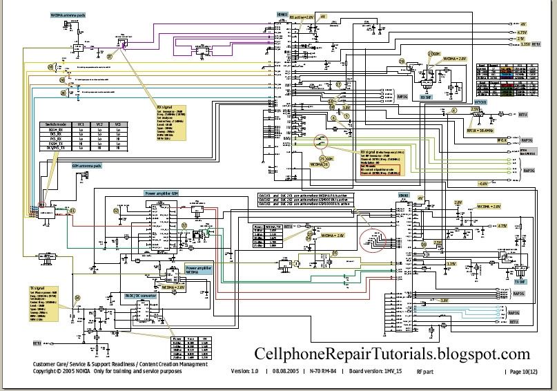
1. Find any available schematic diagram and locate the microphone circuit layout on it. Remember where each parts and components location and do a mapping like this.

2. Use a multi-tester and check the pads for a short circuit, this is not always happen but it is also unpredictable to a mobile phones short circuit might occurs, you are not checking the outer mounted components but the internal lines with it. Just set the tester to x1 resistance value, I preferred analog multitester in this lesson for it is cheaper to purchase rather than the digital. Now connect both test probe to the inner and outer layer of the mouthpiece terminal pads, then do it again in opposite manner, a short circuit have both readings closer to zero ohms.

nokia 6300 mic tracing
3. Trace the line paths between the first or the closest component connected to each terminal pads.
The circuit diagram shows that there are coil filter in both lines, connect the tester across each coil terminal leds, your not just checking the lines here but also checking the the coil as well.


4. Now the next step is to leave behind the line paths between the coil to the EMI-Filter for it is uncheckable beyond that paths for the EMI- filter is an IC. you need to remove it first before you can check on that lines , which will be done later at the last steps of procedures. Now next to move on to the opening lines and component where the test probe can connect with, the two filter capacitors and both coils which are an open path where you can connect the test probe on it. now connect or attach both probes at the end of each line indicated in red.

5. Now check the remaining open path which is the Resistor, you can't check the line paths on those area for it ends up connected to Retu IC. So just then proceed to check its resistance value instead.

6. If all those mentioned lines above is all in good condition you may now proceed to suspect the EMI-Fiter is having a problem or faulty. You then now remove it from the Printed circuit board then do a line check up from the mouthpiece terminal to that EMI-filter terminal bumps where it is being connected.

You can refer to the schematic diagram for each terminal specification. You may now can check the IC itself by analyzing the internal circuitry inside it. I advice just replace a good and working one if not so sure about.

8. It this step is most complicated job to do with, specially for beginners.This is one of advance troubleshooters skills.  If found all of those line paths and components above were in good conditions. The last part is to work a power management IC itself for the audio codec circuit is also within that chips.
Now, if the last and final suspected parts is the chips, you must need to rework it, Reheating it the first will do and might as well also work. But if the problem still remain, Reworking it is the best advice that suites out.
but also do not forget to check the line paths between the mouthpiece circuit area, while the chips is being remove and out on the PCB layout, it is a proper time to check the ball bumps terminal where that certain microphone is being connected. an example of tracing the ball bumps terminals below.
okay, that's it for a while, for there are lots of techniques we are going to tackle sooner, hope you do understand a little bit with this method.

how RF circuit Works on Cell Phones

mobile phone rf circuit block diagram

In cell phone repair it is very helpful to understand how the RF circuits works , for this is a big help when
troubleshooting No signal problem issues.
RF stands for radio frequency , this frequency is used to  transmit and receive the data signals from a mobile phone.

Here's a brief explanation on how does RF circuit works on mobile phones.
This is for GSM RF circuit only, although the WCDMA circuit and WI-FI circuit have similarity on this but I will try to explain both of it hereafter.

See the block diagram below. Observe how the frequency data signal feeds from a certain parts of an RF circuit design.
A breakdown or failure of each certain part will result to signal loss and the capability to generate, amplify, control , process, send and receive the desired radio frequency during transmission process. 
cell phone RF circuit

In mobile phones transmission there are two types of operation took place, the receiving operation and the transmitting operation.
In normal mode, RX part is always active in receiving operation the antenna switch is always open its gateway through to the RX circuit, It is always ready to receive and intercepts the radio waves and wait for the desired frequency signal to catch up.
During transmission like making a call or sending a text message the antenna switch will close the gateway of the RX and open the gateway of the TX in order not to interfere the data signal during transmission.
All data that has been receive and before to transmit or send, all this data signals are feeds to the baseband processor.

An explanation  of an RF Circuit Parts and what possible problems if a certain part is damaged.

RF Receiver - ( RX radio receiver )
The rf receiver are called RX, this circuit is design to receives, and process the data signals from the airwaves during transmission process. A failure of this circuit will result to unable to receive data signal during transmission.

RF Transmitter  - ( TX radio transmitter )
the rf transmitter are called TX which is the one that process, amplify  the data signals from a mobile phone . 
Once failed to initiate  a failure to transmit radio frequency signal, this will result to unable to send data signal during transmission. .

Power amplifier -  RF amplifier
The power amplifier is used to amplify, boost up the radio frequency signal before it feeds to the antenna before it thrown over the air waves during transmission. If damaged will result to signal loss, a dropping signal indication on the display.

The Antenna is used to intercepts and thrown the radio radio frequency in the air  during transmission
When electricity is "thrown" into the metal of an antenna, the metal reacts to the electricity at an atomic level in the form of a wave.
if damaged or due to a corroded terminal pads, will indicate and show a poor signal or low level frequency signal.

Antenna switch
The antenna switch is used as a gateway that controls and manage the frequency to pass through, it switch the RX frequency signal and TX frequency signal during transmission process. literally  the antenna is the signal catcher and likewise the signal thrower. If damaged the gateway to the antenna will be closed and result to network signal indication. 

Crystal oscillator
Generates a desired frequency that feeds to the RX and TX circuits. In mobile phones a Voltage controlled Oscillator (VCO) and Voltage Controlled Temperature Compensated Crystal Oscillator (VCTXO) is used in rf circuit.
If damaged the RX and TX will not work and the RF cicuit is at full failure.

SAW filter
Surface Acoustic Wave filter used as an rf synthesizer to purify  a desired level of frequency. If damaged result also to no network signal indication.

An example of the  RF circuit components layout on a PCB board.
The rf circuit components are often covered with shielding metal case unlike the baseband processor parts which is oftentimes not. This is because frequency is very vulnerable with unwanted radio waves interference and destroys data signals. Using the shielding metal will minimize the radio waves interference.

How LCD Display Interface Circuit work

How LCD Display Interface Circuit works?
An LCD -liquid crystal display is an electronically-modulated optical device made up of any number of pixels filled with liquid crystals and arrayed in front of a light source (backlight) or reflector to produce images in color or monochrome.
They can be optimized for static text, detailed still images, or dynamic, fast-changing, video content.
Old type of LCD are monochrome types which only display one certain color while the modern types are colored ones that can display rich text and images.
LCD's resolution of display depends on the amount of pixels into it, the highest amount designed looks and displays best.

Now, LCd wont work without a light source and a reflector to drive it pixels to form an image information.
This typical block diagram below will help us a brief explanation oh how the LCD can produce an text and images on mobile phones handsets
The block diagram shows the LCD gets a data source from the application processor, so therefore LCD is being controlled by the application processor to produce a detail images,
LED is a light emitting diode that can produce light, this light source of an LED is the one that reflect at the back of an LCD, without this LED light reflection on the back of an LCD  it will result a black or dark screen displays.
LCD also needs a power supply voltage to activate its liquid crystal arrays inside of it, so that is why a voltage supply is also very important for that matter.

display+circuit+block+diagram
 An LCD Display Circuit Schematic diagram of a mobile phones below interprets how the whole circuitry of an LCD being connected and designed. A circuit start from an application processor that controls and sends data to LCD connector which where the LCD is being connected. Before the data reach to the LCd connector it is being filtered for Electromagnet Interference protection. The LED light circuit and a power supply voltage is also provided for it is also work an important part on LCD circuit.
lcd display circuit schematic  diagram
The picture below interprets the schematic diagram above on how  each components layout are being mounted on a particular mobile phones printed circuit board.
Always keep in mind that LCD needs the following sources to make it work completely,
1. Data control signal from the application processor
2. LED light that reflects on it back so that display will reveal completely.
3. A power supply voltage to turn the LCD activated.
 A failure of these three sources will result on display problem issues.

Understanding Mouthpiece or Microphone, Earpiece and IHF or Buzzer Speakers Circuit

A mobile phones microphone or mouthpiece is a component used to convert sound signal into an electrical signal. The earpiece speaker is the one that converts electrical signal into a sound signal, likewise also the IHF , buzzer or ringer speaker do.
These certain parts works as a user interfaces components on a mobile phone.
And controlled by an Audio Codec Circuit which is the part that relatively controls and converts all audio frequency signal.see picture below

A picture below is an schematic diagram microphone or mouthpiece circuit,
A typical and modern designed  of mouthpiece circuit is being protected by an EMI- Filter to prevent sound interruption, before it then feeds the audio signal to the audio codec circuit. Some microphone circuit other mobile phones have no EMI Filter like the one showed below. The microphone line signal is being presented into positive and negative polarity, and those two polarity lines is being filtered again by two capacitor after being pass by from an EMI-Filter, in order to remove the DC (direct current) coming from the EMI-filter.
microphone schematic diagram

The earpiece circuit is also filtered by inductor coil to reduce sound saturation cause by any radio frequency interruption.

 And same also in an IHF speaker circuit. The IHF speaker also have two lines which is positive and negative line.

A vibrator motor although this is not a sound converting device but it generates a vibration which generates sounds, this one is also included in audio circuitry.
Here's an example mapping layout of a Microphone, Earpiece, IHF speakers and Vibrator  motor connections on a mobile phones printed circuit board. Each connection were both separated and apart from each other but all  of each line is being pointed towards in audio codec circuit.
audio circuit
The above picture is only an interpretation of how audio circuit is being connected or mounted in a mobile phones printed circuit board.

Audio amplifier or an audio mixer or a sound booster

The Audio Codec is a circuit that controls sound signals in a cellphone circuits. It acts like an audio amplifier or an audio mixer or a sound booster.
Audio codec is the main area in a mobile phone where all audio properties is being process, during transmission and receiption. It converts the sound signal into radio frequency signal, and also converts radio frequency signal into a sound signals.
Like for example a microphone's sound signal is being amplified then converts and feeds to radio frequency before it send to the network airwaves. Opposite to that process is the conversion of radio frequency into an audible or understandable sound, and that sound is that what we hear on the earpiece speaker.
A typical block diagram below show  how audio interfaces being connected to an audio codec circuit.

audio codec block diagram
The Audio codec is the main part which control all audio properties from all audio interfaces like the microphone, earpiece, IHF (integrated hands free) speaker or a buzzer, ringer, head set and vibrator motor. A typical audio circuit is being filtered from any sound interference signal to avoid sound interruptions.

LED light bulbs works on Mobile Phone Circuit

An LED - light emitting diode is used to illuminate keypads keys and LCD screen displays on all mobile phones handsets. It is being controlled by a voltage or current draws on its terminal leds.
a picture below is an Schematic Diagram that tells us how does the LED circuit works on cellular phone whole circuitry.

On schematic diagram  we notice that the LEDs is driven by an LED driver chip's, and an Switching Control circuit that also being packed in a chip. The LED driver is being used to stabilized the voltage and current and do take control on engaging ON and OFF status of an LEDs to light up or not.
It also drives  the amount  of  brightness or dimming status of the LEDs by applying Pulse Width Modulation signal from the Switching control circuit.

The block diagram below interpreted a component and section or parts of  an LED circuit to work during application process.
The Switching control circuit feeds and release a Pulse Width Modulation Signal (PWM) to switch and light up the LEDs light bulbs. A pulse width modulation signal is a type of digital frequency signal range up to 1khz to enable and implement to take control of  LED brightness.
Once that certain signal is being received by the LED driver, the LED driver now will engage and release the voltage or current that being feeds up from the mobile phones battery supply voltage;
The output voltage release by the LED driver is the one that draws the LED light bulbs to light up.


LED drivers is a high frequency, synchronous boost converter with constant current output to drive up to 5 white LEDs. This device circuit is designed  for maximum safety,  it integrates overvoltage  and short circuit protection when the output is being shorted to the ground. Meaning this chips circuitry will not easily  breakdown for it is designed to protect when short circuit happens.
like for example, the two LED light bulbs commits short circuit to its terminal
In mobile phones application methods; the switching control circuit that release pulse switching signal is also being synchronized programmed by the the application processor (CPU) to engaged a full control on how and which proper situation that the LED will be switch to light up or not.
like for example the LED will only switch and light up, if the handset is being in used and remain off if the handset is not in used.
The above image is an example of the LED circuit, how those particular stages and components being mounted on a phones circuits. Note that the LED driver and switching control circuits is being packed into an Integrated Circuit or ICs.


To all beginners: A bunch of simplified STEP By STEP Procedures On Troubleshooting LED Problem issues on various mobile phones  product will be Posted Here Later.. Just keep on visiting this blog more often.

Cellphone's Schematic Diagram

How to Read Cellphone's  Schematic Diagram?


Schematic Diagram is a layout of symbols and and connection of every electronic components circuit  where serve as a guide on how the circuit function or work.
Reading Schematic Diagrams is not a hard task to do, schematic diagrams is a big help to cellphone-repair
especially when working on or tracing  lines and finding where a particular components mounted on a PCB board.
Such schematic diagrams is very useful and very important guide in every cellphone technician. It is equivalent to a handbook.
Learn how to read it. At first you might think that it is hard to do so, You are not going to be an  experts and master in cellphone repair as long as you don't know how to read it. Many among cellphone repairman exist nowadays  that do not have any knowledge about reading it. They always rely on finding free solutions over the internet and forums. Those people who give free solutions are those people who knows how to read a schematic diagram. Now here's your chance to learn and do not rely unto others, and be an expert and master troubleshooter when it comes to hardware problems.

Okay here's a step on how to read a schematic diagrams.

1. You need to download service Schematic Diagrams, as many or complete package in every cellphone products. each unit of a product have specific service diagrams.

2. You need to download Adobe Acrobat Reader so that you can open the schematic file which is in PDF format.

Now assuming that you already have those I've mention above; Let's try to open up one file like for example we are going to open a schematic diagram of  Nokia N70.

here's what it looks  like when scrolling down all the pages.
Let's take a little brief on each page  for simple understanding..


A. page 1, In this page where you can find and Identify the whole assembly of the unit.
                 this is also where to findd  the table of contents of the entire circuit's layouts.


B. page 2, In this page is a block diagram of an RF and Baseband: this is a basic explanation of  the entire connection of a circuit. It was called  a block diagram for it is being drawed  into blocks.

What is a BASE BAND?
In telecommunications and signal processing, baseband is an adjective that describes signals and systems whose range of frequencies is measured from zero to a maximum bandwidth or highest signal frequency; it is sometimes used as a noun for a band of frequencies starting at zero. It can often be considered as synonym to lowpass, and antonym to passband, bandpass or radio frequency (RF) signal.


What is a RF?
Radio frequency (RF) is a frequency or rate of oscillation within the range of about 3 Hz to 300 GHz. This range corresponds to frequency of alternating current electrical signals used to produce and detect radio waves. Since most of this range is beyond the vibration rate that most mechanical systems can respond to, RF usually refers to oscillations in electronics circuits.


C. page 3, here we can find the system connectors and parts of the unit that correspond to the user or outer parts such us headset, charger and USB connection interfaces.


D. page 4, The  power management circuit, audio codecs and drivers and the interfaces like the microphone, earpiece, mouthpiece, vibrator, sim-card, battery connections. This is the Power Supply Area of the entire circuits.


E. page5, Charging Control and Flash Interface Circuit.


F. page 6, This is the part of the circuit where the all application is being process, Flash IC and memories, this also where application and firmware are being stored.


G. page 7, his the Central processing of the unit (CPU) like the personal computer (PC) cellphone also have a CPU to process applications and software.


H. page 8, A Frequency Modulation (FM Radio) circuit.


I. page 9,This page is the part of an LCD Display and Keypad circuit.


J. page 10,  this is the RF components circuit, In this page the RF or the process of a network during Transmitting and Receiving Radio Frequency signals.


K. page 11, This the structure  of the whole PCB Board and all the components mounted in the entire circuit.
                    this is also where pattern of   test-points  for check-up during production and servicing.
at the right side is the pattern of waves of frequencies as a guide by using an oscilloscope, frequency  generator and spectrum analyzer.


L. page 12,  This is where  the table of each and every components is mounted on the PCB board written in codes, like Rxxx - resistorr, Cxxx - Capacitor and etc.
The right side is the scale pattern of every components for quick and easy finding it.


that was only the brief explanation of every pages of an Schematic Diagram. Further we will tackle on it even deeper.
Related Posts Plugin for WordPress, Blogger...

New Post Here:


Copyright @ 2013 Rayerbazar Mobile.