A mobile phones microphone or mouthpiece is a component used to convert sound signal into an electrical signal. The earpiece speaker is the one that converts electrical signal into a sound signal, likewise also the IHF , buzzer or ringer speaker do.
These certain parts works as a user interfaces components on a mobile phone.
And controlled by an Audio Codec Circuit which is the part that relatively controls and converts all audio frequency signal.see picture below
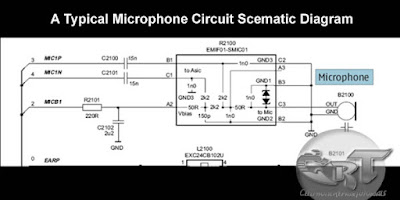
 A picture below is an schematic diagram microphone or mouthpiece circuit,
A typical and modern designed of mouthpiece circuit is being protected by an EMI- Filter to prevent sound interruption, before it then feeds the audio signal to the audio codec circuit. Some microphone circuit other mobile phones have no EMI Filter like the one showed below. The microphone line signal is being presented into positive and negative polarity, and those two polarity lines is being filtered again by two capacitor after being pass by from an EMI-Filter, in order to remove the DC (direct current) coming from the EMI-filter.
The earpiece circuit is also filtered by inductor coil to reduce sound saturation cause by any radio frequency interruption.

And same also in an IHF speaker circuit. The IHF speaker also have two lines which is positive and negative line.

A vibrator motor although this is not a sound converting device but it generates a vibration which generates sounds, this one is also included in audio circuitry.
 Here's an example mapping layout of a Microphone, Earpiece,
IHF speakers and Vibrator motor connections on a mobile phones printed
circuit board. Each connection were both separated and apart from each
other but all of each line is being pointed towards in audio codec
circuit.
Here's an example mapping layout of a Microphone, Earpiece,
IHF speakers and Vibrator motor connections on a mobile phones printed
circuit board. Each connection were both separated and apart from each
other but all of each line is being pointed towards in audio codec
circuit.
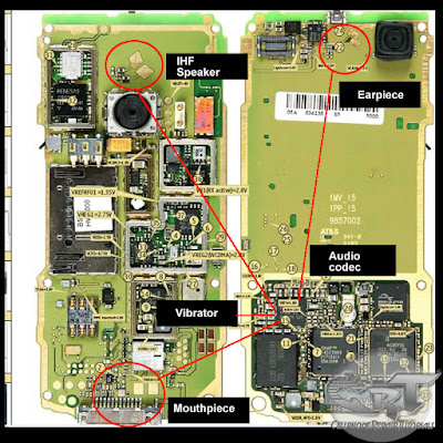 The above picture is only an interpretation of how audio circuit is being connected or mounted in a mobile phones printed circuit board.
These certain parts works as a user interfaces components on a mobile phone.
And controlled by an Audio Codec Circuit which is the part that relatively controls and converts all audio frequency signal.see picture below

A typical and modern designed of mouthpiece circuit is being protected by an EMI- Filter to prevent sound interruption, before it then feeds the audio signal to the audio codec circuit. Some microphone circuit other mobile phones have no EMI Filter like the one showed below. The microphone line signal is being presented into positive and negative polarity, and those two polarity lines is being filtered again by two capacitor after being pass by from an EMI-Filter, in order to remove the DC (direct current) coming from the EMI-filter.

The earpiece circuit is also filtered by inductor coil to reduce sound saturation cause by any radio frequency interruption.

And same also in an IHF speaker circuit. The IHF speaker also have two lines which is positive and negative line.

A vibrator motor although this is not a sound converting device but it generates a vibration which generates sounds, this one is also included in audio circuitry.


0 comments:
Post a Comment