In cell phone repair it is very helpful to understand how the RF circuits works , for this is a big help when
troubleshooting No signal problem issues.
RF stands for radio frequency , this frequency is used to transmit and receive the data signals from a mobile phone.
Here's a brief explanation on how does RF circuit works on mobile phones.
This is for GSM RF circuit only, although the WCDMA circuit and WI-FI circuit have similarity on this but I will try to explain both of it hereafter.
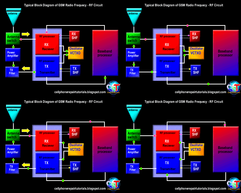
See the block diagram below. Observe how the frequency data signal feeds from a certain parts of an RF circuit design.
A breakdown or failure of each certain part will result to signal loss and the capability to generate, amplify, control , process, send and receive the desired radio frequency during transmission process.

In mobile phones transmission there are two types of operation took place, the receiving operation and the transmitting operation.
In normal mode, RX part is always active in receiving operation the antenna switch is always open its gateway through to the RX circuit, It is always ready to receive and intercepts the radio waves and wait for the desired frequency signal to catch up.
During transmission like making a call or sending a text message the antenna switch will close the gateway of the RX and open the gateway of the TX in order not to interfere the data signal during transmission.
All data that has been receive and before to transmit or send, all this data signals are feeds to the baseband processor.
An explanation of an RF Circuit Parts and what possible problems if a certain part is damaged.
RF Receiver - ( RX radio receiver )
The rf receiver are called RX, this circuit is design to receives, and process the data signals from the airwaves during transmission process. A failure of this circuit will result to unable to receive data signal during transmission.
RF Transmitter - ( TX radio transmitter )
the rf transmitter are called TX which is the one that process, amplify the data signals from a mobile phone .
Once failed to initiate a failure to transmit radio frequency signal, this will result to unable to send data signal during transmission. .
Power amplifier - RF amplifier
The power amplifier is used to amplify, boost up the radio frequency signal before it feeds to the antenna before it thrown over the air waves during transmission. If damaged will result to signal loss, a dropping signal indication on the display.
The Antenna is used to intercepts and thrown the radio radio frequency in the air during transmission
When electricity is "thrown" into the metal of an antenna, the metal reacts to the electricity at an atomic level in the form of a wave.
if damaged or due to a corroded terminal pads, will indicate and show a poor signal or low level frequency signal.
Antenna switch
The antenna switch is used as a gateway that controls and manage the frequency to pass through, it switch the RX frequency signal and TX frequency signal during transmission process. literally the antenna is the signal catcher and likewise the signal thrower. If damaged the gateway to the antenna will be closed and result to network signal indication.
Crystal oscillator
Generates a desired frequency that feeds to the RX and TX circuits. In mobile phones a Voltage controlled Oscillator (VCO) and Voltage Controlled Temperature Compensated Crystal Oscillator (VCTXO) is used in rf circuit.
If damaged the RX and TX will not work and the RF cicuit is at full failure.
SAW filter
Surface Acoustic Wave filter used as an rf synthesizer to purify a desired level of frequency. If damaged result also to no network signal indication.
An example of the RF circuit components layout on a PCB board.
The rf circuit
components are often covered with shielding metal case unlike the
baseband processor parts which is oftentimes not. This is because
frequency is very vulnerable with unwanted radio waves interference and
destroys data signals. Using the shielding metal will minimize the radio
waves interference.


0 comments:
Post a Comment